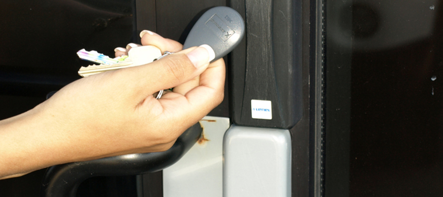
RFID projects have been pretty prominent recently, ranging from projects here in Indestructible, to our local Silicon Chip magazine in Australia publishing a RFID key door lock project in.
Step 1: How does RFID work?
RFID, or Radio Frequency Identification is the term used to describe a wide variety of standards that allow data stored within electronic ‘tags’ to be read by a reader.
Step 2: Whats stored on the card?
I started by building a RFID smart card reader (more details in a future article). That showed me the data that was being sent when the card transmitted its.
Step 3: How do we emulate a card?
So the next step was to identify how to pretend to be a card – I wanted a card that I could type a card number into.
Step 4: The Software – Entering data into our card
The software was next. Using the Arduino IDE, I implemented a simple menu system that allowed me to enter the relevant facility and Card ID data directly from the.
Step 5: Etching the PCB
As per standard, I used toner transfer onto magazine paper to etch a board. If you want to see the details, have a look here. The etched PCB.
Step 6: Mounting the components
To keep the project the same size as a normal proc card, I decided to make it on a small PCB that was the same size as a.
Step 7: Programming the Micro
I used a standard 6 pin header mounted on the PCB to allow a FTDI 5V USB-232 cable to be used to program the chip in-situ.
Step 8: Testing the project
Testing was a breeze – I typed the relevant code into the keypad, swiped the board against the reader, and was rewarded with a satisfying ‘BEEP’ indicating that.
Step 9: Further steps
This was a ‘to prove I could do it’ project – I have completed it, so it now sits on my shelf at work to remind others that.


